
Rotary Encoder
Rotary Encoder
Rotary Encoder
Measurement System
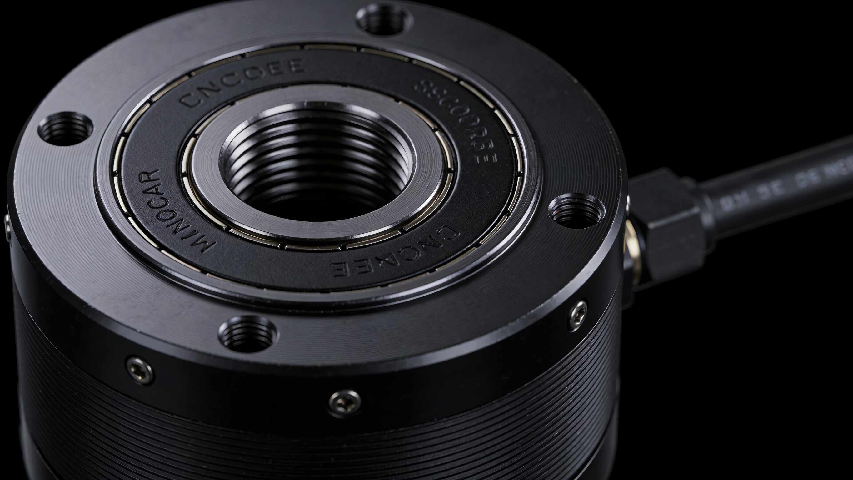
A rotary encoder tailored for low-voltage precision motion control, designed to meet the critical demands of miniaturization, high accuracy, and high reliability. Featuring a non-contact reflective disk design with a corrosion-resistant metal disk that matches the thermal expansion coefficient of the housing, paired with a high-resolution read head, it delivers position feedback within ±1um/rad. Perfectly suited for low-voltage ultrasonic motors, low-voltage stepper motors, and other micro servo systems. Widely used in industrial automation actuators and precision drive devices, it enables precise closed-loop control of position and speed.
Key Features
- •Contactless design for precision and longevity: The encoder system uses a contactless reflective design with no mechanical wear, delivering precise position feedback and extended service life.
- •High Resolution and Accuracy: Single-turn resolution up to 18432 pulses, position accuracy ±1um/rad, repeatability ±0.5um/rad — designed for high-precision motion control.
- •Universal Material Compatibility: Features a high-corrosion-resistance metal encoder disk with a thermal expansion coefficient matched to the motor shaft, ensuring precision stability across extreme temperatures and harsh environments.
- •Easy to install with visual status monitoring: Built-in setup LED for faster installation and debugging; real-time system fault detection via LED color (green = normal, red = error).
- •High environmental adaptability: Operates reliably from -10 to 70°C, features IP40 protection rating, and withstands vibrations up to 100m/S², designed for demanding industrial environments.
- •High Reliability Connection: Equipped with an 8P FFC cable, rated for over 1500K bend cycles to ensure long-term durability without contact failure risks.
- •Dual Voltage Support: Offers 3.3V/5V voltage options to meet the power requirements of various low-voltage motors.
Metal Code Disk Specifications
| No. | Technology Category | Core Specifications | Notes |
|---|---|---|---|
| 1 | optical zero | 1 per lap | Precise Positioning Reference |
| 2 | Location Accuracy | ±1um/rad | High-precision position feedback |
| 3 | Repeatability | ±0.5um/rad | Consistent performance over extended operation |
| 4 | Pitch | 113um | Core Parameters for Signal Parsing |
| 5 | Material | High-corrosion-resistant metal with matching coefficient of thermal expansion | High and low temperature, no precision drift |
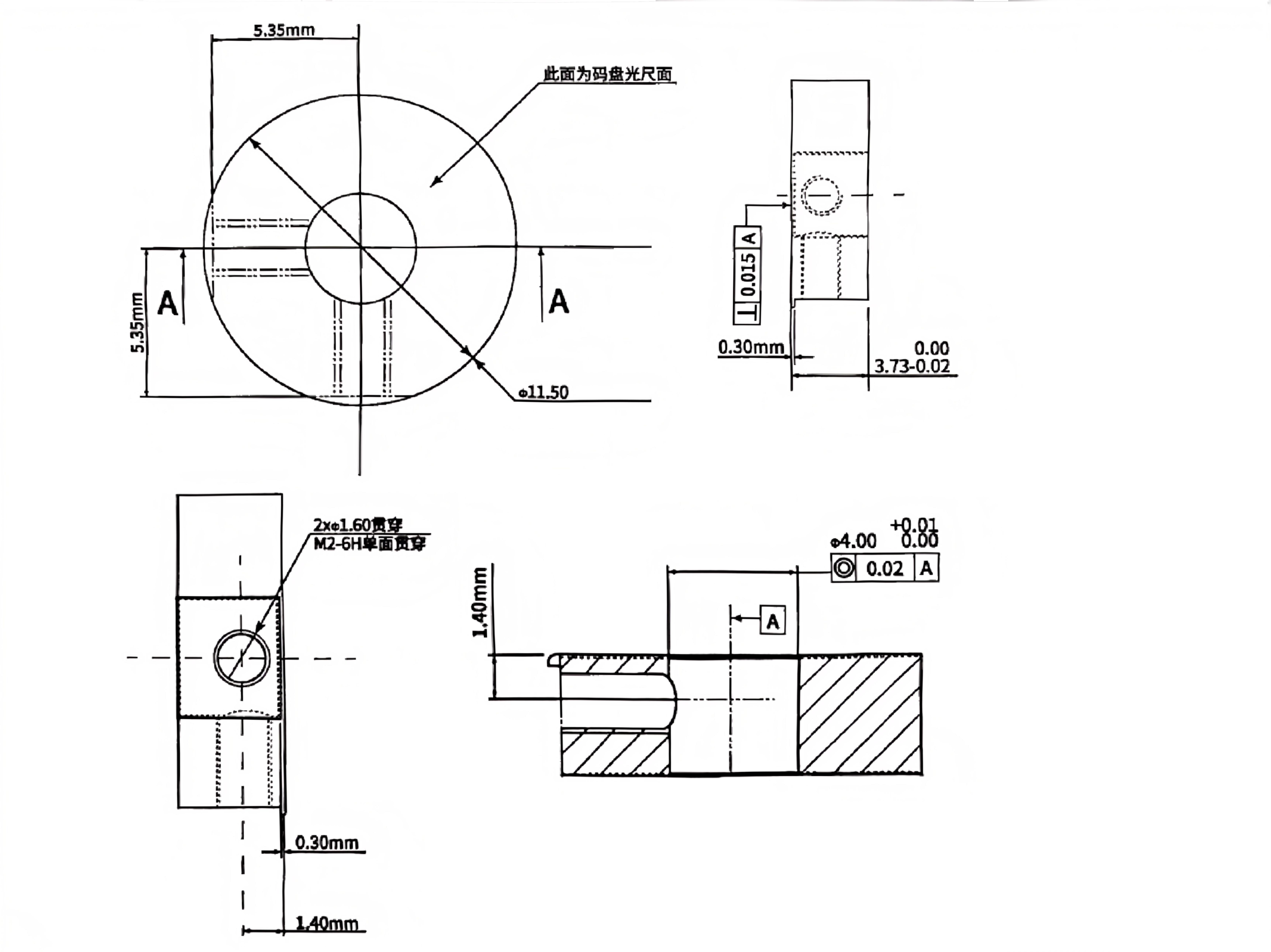
| 6 | Dimensions | Diameter 11.5mm | Designed for lightweight mini motors |
Read Head Specifications
| No. | Technology Category | Parameters | Notes |
|---|---|---|---|
| 1 | Model ID | ASMR-01633-U1 / ASMR-01605-D1 | Distinguish Voltage Versions |
| 2 | Rated Voltage | 3.3V DC / 5V DC | Supports various low-voltage motor power supplies |
| 3 | Operating Current | < 200mA | Low-power design for energy efficiency |
| 4 | No-load current | < 50mA | Lower standby power consumption |
| 5 | Single-turn resolution | 18432 pulses/rev | High-resolution signal output |
| 6 | Max Interpolation | 16X | Improve signal parsing accuracy |
| 7 | Maximum RPM | 434 rev/sec | Optimized for high-speed motion scenarios |
| 8 | Seismic Resistance Grade | Max 100m/S² | Robust anti-interference capability for industrial environments |
| 9 | Operating Temperature | -10℃~70℃ | Wide-temperature range for harsh operating conditions |
| 10 | Operating Humidity | RH < 90% (non-condensing) | Avoid signal interference in damp environments |
| 11 | Protection Rating | IP40 | Dustproof protection, designed for industrial environments |
| 12 | Connection Cable | 8P FFC Cable (Bend Life > 1500 K Cycles) | Highly Reliable Connection |
| 13 | Status Indicator | Green light = Normal, Red light = Abnormal | Visual Troubleshooting |
| 14 | Output Signal | ABZ differential signals | Compatible with mainstream servo control systems |
Installation Instructions
1. Preparation:Clean the encoder scale and readhead optical surfaces to prevent dust or oil from blocking the light path.
2. Encoder assembly:Secure the encoder disk to the motor shaft using M2 screws, ensuring the concentricity of the Φ4.00 mounting hole with the shaft is ≤ 0.02mm.
3. Read head alignment:Install the read head, strictly controlling the gap to the scale disc at 0.30mm and end-face runout ≤ 0.015mm.
4. Wiring and debugging:Connect the 8P FFC cable and power on. Observe the LED: a solid green light indicates installation or signal is normal; a red light means you need to adjust the gap or coaxial alignment.
5. Parameter Calibration:Integrate control system to verify ABZ signals and resolution parameters, completing closed-loop debugging.
6. Troubleshooting:When the red light indicates an error, first check installation clearance, coaxiality, and wiring contact. Then verify that the supply voltage matches specifications.
7. Lifespan:Contactless design eliminates mechanical wear. FFC cable bending life reaches 1500 10K cycles; normal service life is ≥5 years (industrial applications).