
Linear Encoder
Linear Encoder
Linear Encoder
Measurement System
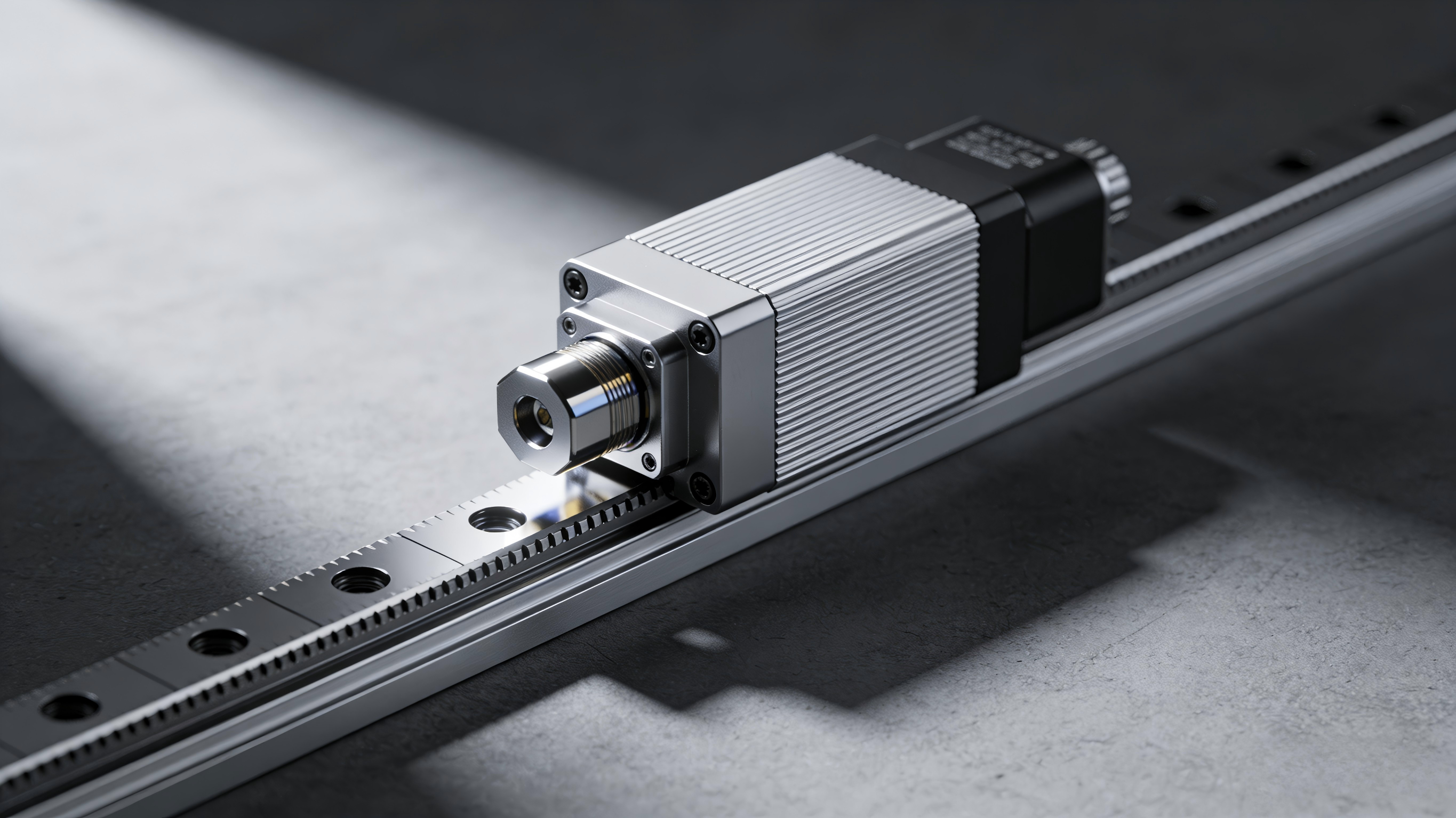
The ASML series linear optical encoder features a non-contact reflective photoelectric design with a highly corrosion-resistant stainless steel scale tape, delivering standard AquadB incremental square-wave signals. Equipped with internal interpolation circuitry and LED status indicators, it offers easy installation and debugging with stable, reliable operation. Widely used in high-precision linear displacement feedback applications such as linear motors, semiconductor processing, LED packaging, machine vision, precision metrology, and X-Y stages.
Key Features
- •Non-contact reflective design: wear-free, long-lasting, and highly stable
- •Pitch 64μm, Position Accuracy ±3μm/m, Repeatability ±0.7μm/m
- •Supports adjustable multi-resolution with 0.1μm, 0.5μm, and 1μm.
- •Maximum operating speed: 8 m/s; acceleration up to 400m/s²
- •Optical zero reference every 32mm for clear positioning
- •Built-in LED indicator: green for normal, red for error, enabling quick debugging
- •8-core shielded ultra-flexible cable, bend life > 1500k cycles
- •Clear system faults in real time via LED color.
- •Industrial-grade wide-temperature operation: -10°C to 70°C, IP40 protection rating
Selection Guide
| Product Model | Core Specifications | Use Cases |
|---|---|---|
| ASML-280Z-8 | Range 280mm, blade width 8mm | Short-stroke precision stage, compact equipment |
| ASML-1030Z-6 | Range 1030mm, blade width 6mm | Long-stroke linear motors, large-scale automated production lines |
| ASMR-00505-L1 | 0.5μm resolution, up to 8 m/s | High-speed motion platforms, linear motors |
| ASMR-00105-L2 | 0.1μm resolution, up to 1.6m/s | High-precision detection and precision positioning scenarios |
Installation Instructions
1. Grating ruler installation:Ensure the mounting surface is clean, dry, and free of oil. Use the dedicated fixture for installation; do not scratch the scale face with hard objects. After installation, clean the scale face with a lint-free cloth.
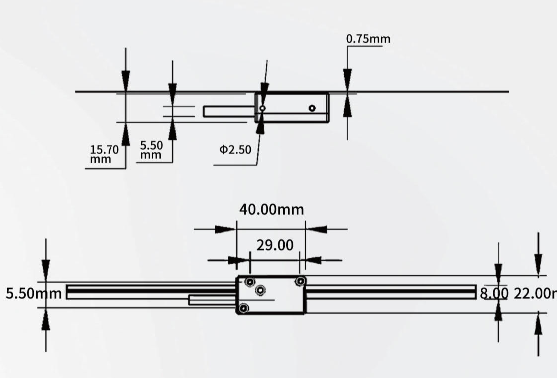
2. Install the reading head:Adjust the gap between the readhead and scale to 0.75mm until the green LED stays on; ensure the mounting bracket is rigid; do not touch the optical window with your hands.
3. Wiring Requirements:Use twisted-pair shielded cable with single-point reliable grounding. Do not connect or disconnect connectors while powered to prevent module damage from static electricity or surges.
4. Power-on debugging:Green light = Normal operation; Red light = Installation gap anomaly or signal fault, requires realignment.
5. Routine Maintenance:Clean the scale strip regularly with isopropyl alcohol or anhydrous ethanol. Check that mounting screws are tight. Avoid use in dusty, oily, or corrosive environments. Higher resolution requires a cleaner scale surface.